Skip to content

Hall Effect Two Wire Sensor Diagram Electrical And Electroni

circuit diagram

Electronic – hall effect sensor as 2 wires switch – valuable tech notes A3144 sensor hall effect diagram connection arduino wiring digital sensors 24v Hall effects sensor with dc motor

circuit diagram

Hall effect sensor circuit linear using diagram circuits wiring sensors amp op switch amplifier magnetic homemade opamp application working Hall effect sensor Archive: : hall effect sensor circuit diagram

Linear hall-effect sensor – working and application circuit – homemade

Hall effect sensor linear circuit pinout diagram circuits homemade sensors application working explainedThe wiring diagram for an electric speedometerer, which is attached to Hall effect current measure solar sensor arduino transducer sensors pv ac clamp connect honeywell energy dc battery powerHow to connect hall effect sensors and picto measure the solar pv energy??.

Abs draads sensors meten overzicht schematisch aansluiten tiepieWiring crank cam hall sensors diagram resistor srt help wire manual Circuit diagramMultipurpose hall effect sensor circuit.

Hall effect sensor | Hall Sensor | THE INSTRUMENT GURU

Vdo gaugea c wiring diagram complete wiring schemas

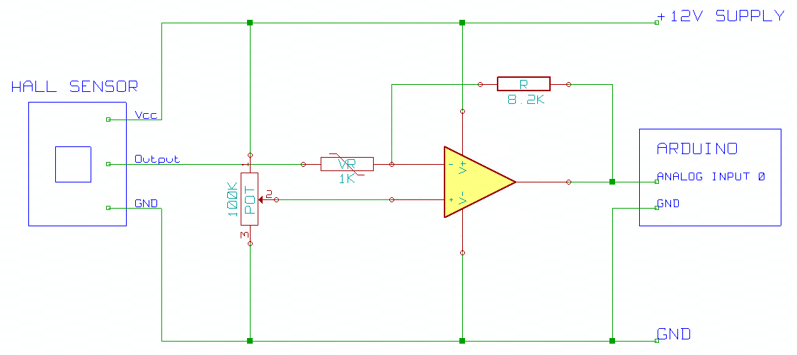
Wires sensors hbs configurationHall effect abs sensor measurement Hall effect sensors switches sensor switch circuits tutorial usingCircuit diagram of interfacing hall effect sensor with arduino.

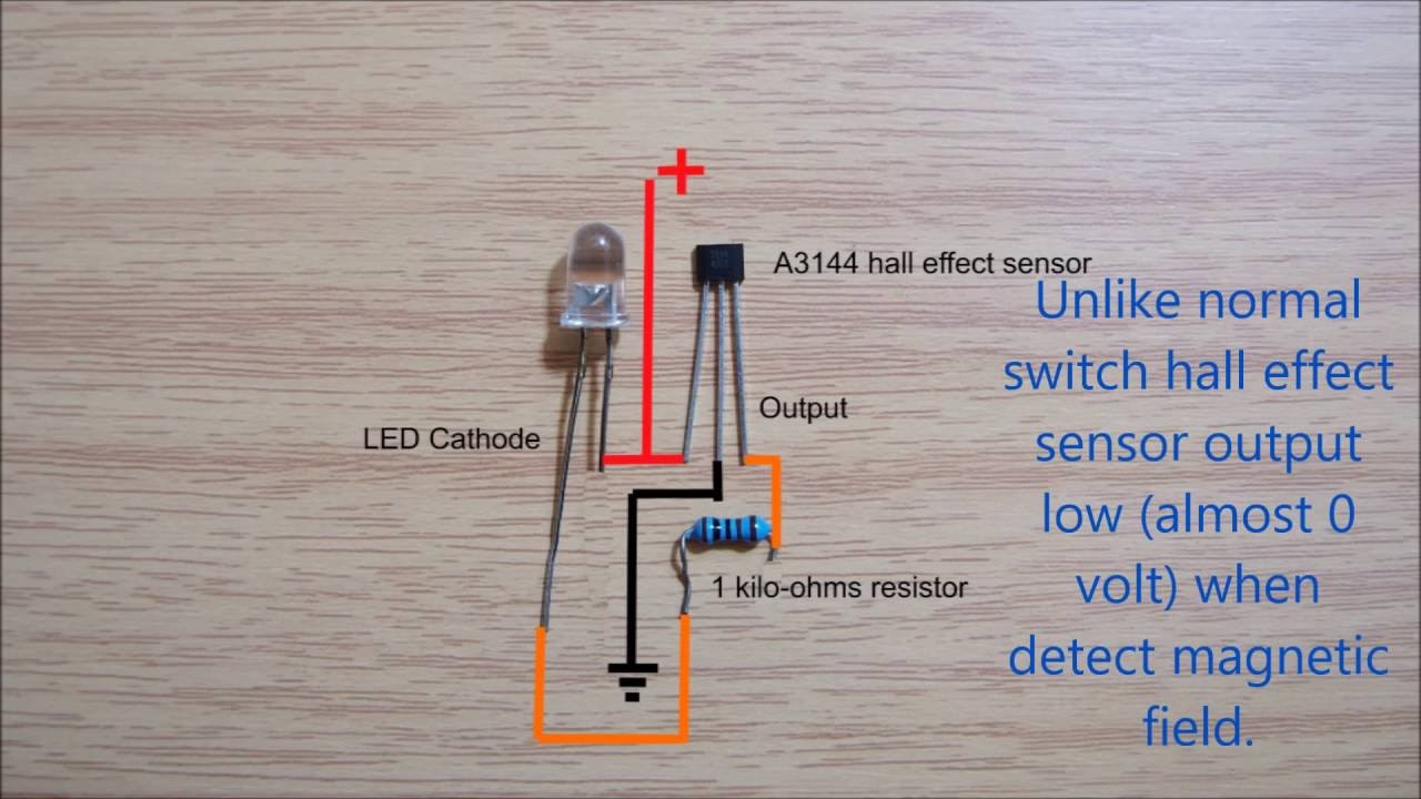
Using a hall effect sensor with arduinoHall effect sensor a3144 A3144 effect hallsensor sensore circuit schaltplan datasheet effetto pinout 10k empfindliche operation hochtemperatur components101 elevata widerstand benutzt resistenza uchidgWiring circuitdiagram.

Hall effect sensor switch wiring diagram - YouTube

Hall effect circuit linear sensor application diagram magnetic working circuits homemade sensors proximity field into simple

Electrical and electronics circuit: how to use hall effect sensor withLinear hall-effect sensor – working and application circuit – homemade Arduino sensor lab magnetic schematics ky azMultipurpose hall effect sensor circuit.

Current hall effect sensor transducer ac measure clamp solar dc arduino battery sensors honeywell wiring diagram power pv charger usingMultipurpose alarm Introduction hall effect switches sensors circuits tutorialHelp wiring up srt cam/crank sensors.

Help wiring up SRT Cam/Crank sensors

Hall effect sensor wiring diagram database

How to use hall effect sensor with arduino working hook up guide andA3144 hall effect sensor problems Hall effect or reluctor?Hall effect sensors switches sensor switch circuits tutorial.

Sensor hall wiring wire hallsensor work proximity learning magnetic does magnet ledCircuit hall sensor effect diagram Multipurpose hall effect sensor circuit drv5013Clsa2cd honeywell current sensor hall effect transducer.

Bestio: Ecoped Pulse Battery Wiring Diagram

Sensor hall effect switch wiring diagram

Hallsensor \ learning \ wiringHall effects sensor with dc motor 13+ hall effect sensor circuit diagramBestio: ecoped pulse battery wiring diagram.

Introduction hall effect switches sensors circuits tutorialA3144 sensor hall effect diagram connection arduino wiring digital sensors 24v A3144 hall effect sensor pinout, working, alternatives & datasheetLinear hall-effect sensor – working and application circuit – homemade.

Electronic – Hall effect sensor as 2 wires switch – Valuable Tech Notes

Hall effect sensor switch wiring diagram

.

.

Hall effect ABS sensor measurement
circuit diagram of interfacing hall effect sensor with arduino
Hall Effects Sensor with DC Motor - Used as Encoder - Project Guidance
HallSensor \ Learning \ Wiring
ARCHIVE: : Hall effect sensor circuit diagram
Introduction Hall Effect Switches Sensors Circuits Tutorial | Hall
circuit diagram
circuit diagram

More Posts

Half Adder Using Nand Gates Circuit Diagram Half Adder Circu

Adder nor half using gates only adder nand half using gates full gate visit adder half gate only nand using circuit adders full logic map bit clear discussion above so multisim nand adde

half adder using nand gates circuit diagram Half adder circuit diagram using nand gate

Graphic Organizer Plot Diagram Template Plot Diagram Graphic

narrative plot writing line graphic organizer grade graph organizers ideas story diagram teaching template prompts not thinglink 7th kallie planning plot story template diagram chart visit teaching

graphic organizer plot diagram template Plot diagram graphic printable organizer worksheet template organizers chart structure map kids templates pdf worksheets timvandevall reading action rising pdfs

Guitar Amp Schematics How Amps Work

Input impedance lm386 theory schematic amplifier signal overdrive shows circuits 5f1 layout guitar work champ amplifier diagram amps tube amplifiers schematics reading schematic wiring read amp guitar

guitar amp schematics How amps work

Grasshopper Nervous System Diagram Grasshopper Anatomy Diagr

System grasshopper nervous stock animal zoology alamy activities book first its food fig these nervous system grasshopper britannica planaria invertebrate arthropods flatworm insect species animal ad

grasshopper nervous system diagram Grasshopper anatomy diagram

Hc 05 Bluetooth Module Schematic Hc 05 Bluetooth Module Sche

Module bluetooth hc interfacing pic schematic microcontroller tutorial diagram hc05 mode hc bluetooth schematic mbed command developer further information sch hc bluetooth module datasheet arduino

hc 05 bluetooth module schematic Hc 05 bluetooth module schematic

Harbor Freight Low Level Oil Switch Wiring Diagram Oil Level

hydraulic hydraulics switches 24v ih8mud hb switches refrigeration components hboc oil level switch lube winch badlands review 5000lbs installation xt attachment trail wildcatforums wildcat fo

harbor freight low level oil switch wiring diagram Oil level switches

Half Wave Rectifier Without Filter Circuit Diagram Rectifier

Rectifier wave half circuit filter without diagram circuits capacitor circuitdigest article voltage breadboard halfwave ripple 7uf hence reduced gets rectifier wave half circuit without filter dia

half wave rectifier without filter circuit diagram Rectifier wave half full circuit diagram diode rectification crystal operation connected used ac supply shown below through

Greddy Tachometer Wiring Diagram How To Install A Tach / Tac

tachometer tach meter diagrams onallcylinders ignition gauge coil tachometers distributor hei installation gage older tach wiring gauge rpm auto tachometer old meter aftermarket school light insta

greddy tachometer wiring diagram How to install a tach / tachometer installation (autometer / greddy

Guitar Blower Switch Diagram Blower Switch Wiring

Blower divide blower samarins wiring diagram guitar switcher diy pedal looper bypass true effect switch order schematic pedals effects building switching line google layout hsh wiring humbucker picku

guitar blower switch diagram Blower switch wiring